The fibers are getting closer and closer to the chipset. Bringing the data by light to the point where it is centrally processed is one of the main goals of architecture designers. What are the current possibilities for this? Which media types are available? What should one focus on when looking for interconnection solution? This article gives you the answers to these question.
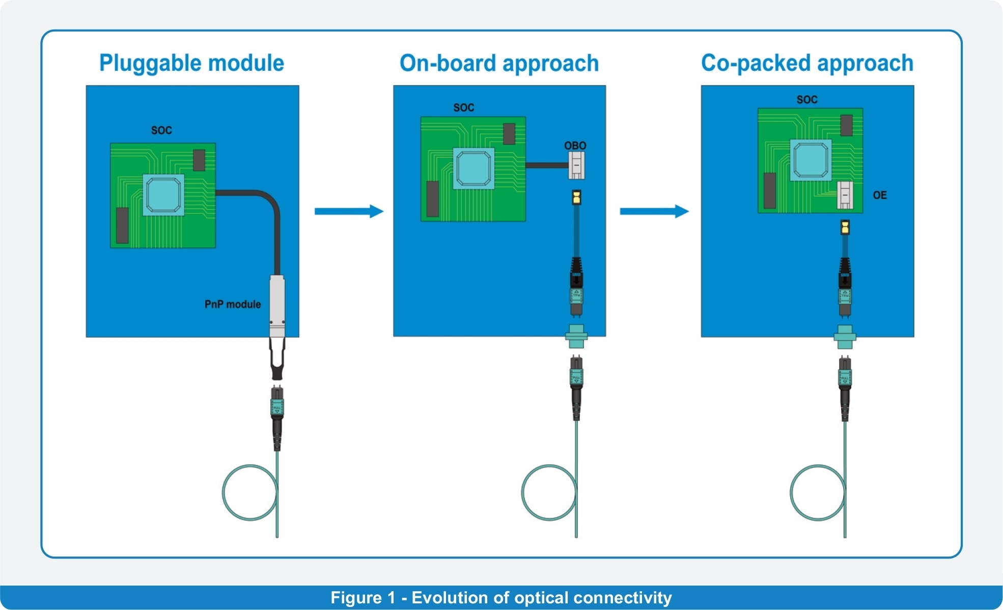
Progress in the field of optics implementation into electronics is clearly pointing at the trend of shrinking the distance between the optical and electrical part on the active PCB. There is a tendency to get the optical part to the same level as the location of the SoC (System on Chip) – to create one complete part. Figure No. 1 shows the genesis of this development. The current front-runner and standard solution is based on the approach of pluggable modules. These modules are located on the border of the inside and outside ecosystem. In this way, they are literally splitting the optical and electrical part. The main disadvantages of this solution are bigger dimensions , lower density of the possible connections, demanding energy consumption and cooling. The second generation is represented by OBO (On-Board Optics) modules, where the opto-electrical convertor is already on the level of the PCB, but still as a separate part. The fully implemented optical part, known as the co-packed solution, will be covered by the 3rd generation, which is still under final development.
Interfaces
The emerging trend is the On-Board Optics approach. Typical representatives are solutions such as Firefly (SAMTEC), BOA (II-IV), MiniPod and MicroPod (BROADCOM), LightAble (REFLEX Photonics), Leap (Amphenol), as well as Intel and TE connectivity designs. Each of those companies has its own design of OBO connectivity to the optical fibres. Inprinciple there are two of them:
• Optical fibres are directly connected into the OBO module (during the manufacturing process) without any possibility of disconnection.
• Optical fibres are terminated into the interface, which allows multiple mating and un-mating cycles.
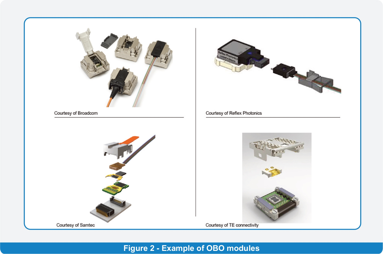
The second option uses either standard mutlifibre MT ferrules (used in MPO /MTP® connectors) or special ferrules designed and dedicated for this purpose. The MT approach utilises the physical contact principle, whereas the special ferrules are based on the lens principle (for example Prizm® LightTurn® from USConec). Figure No. 2 shows some examples of the OBO modules and their optical interfaces.
An equally important aspect is the way the OBO module is connected to the PCB itself. The most commonly used approach is a permanent soldered connection of the OBO to the PCB; however, for example the Samtec solution is designed for multiple connections thanks to the special high-density electrical on-board connectors. To connect the OBO with the outside environment, different types of optical connectors are used depending on the individual requirements of the whole system. Because of the high bandwidth and transmission capacity requirement, the most used connectors are the multifibre ones.
MPO/MTP® connector – optical fibres are terminated into a thermoplastic ferrule. The end face of the ferrule and the fibres are polished to a high level of cleanliness and quality. Mated fibres in this type of connector create a physical contact. Through this physical contact, the highest quality optical connection is ensured.
MXC® connector – in this case, the optical signal is transmitted between the connectors in an enlarged light beam with a larger outer diameter than the fibre core itself. This is achieved by lenses which change the light beam diameter and are responsible for focusing the signal back to the fibre core. This type of connection is less sensitive to dust and impurities as the light beam has a really big spot. On the other side, the overall optical loss is higher compared to MPO-based connections.
The VSFF (Very small form factor) connector family represents the latest generation of single-fibre connectors, characterised by a very high density of fibres relative to the connector footprint. It is based on the mature technique of fibre termination using a 1.25mm ceramic ferrule. This connector enables even a 3-fold fibre density compared to the traditional small-form-factor LC connector and is considered as the most probable candidate for QSFP DD and SFP DD-based applications.
MIL/AEROSPACE is a connector family used in an application with a specific environmental requirement. Typical representatives are the M29504 and
ARINC 801 termini-based interfaces.
The connection media
Both connection points, in terms of the OBO side as well as the outside environment interface, are interconnected by fibre optic media. In practice, two basic designs of this media are used. The first one is a round cable with a protective outer jacket which can also contain a Kevlar-based strength member. The advantage of this design is the freedom of manipulation, especially in more complex routings where the connection media is exposed to multiple bends. The drawback is in its bigger space requirement and the lack of a stacking option when multiple OBO modules are present on the PCB in one row. These disadvantages are solved by using the second design – ribbon style cable which has factory-made and precise geometry, shape and dimensions, which are real benefits during the termination process. The diminutive dimensions are also ideal for the stacking feature on the PCB.
Given the specific usage of the connectivity media, it is important to consider a couple of points during the:
• design phase – when the media is selected
• manufacturing – when the termination is done
• final usage – when the media is connected to the real application
As mentioned at the beginning of this article, the goal is to bring the fibre as close as possible to the SoC. This means keeping the distances where the real fibre connections are implemented as short as possible compared to the typical harnesses used to connect the QSFP or SFP modules. Due to this reason, there are more strict requirements for the precision of the final length as there is no room on the inside of the device for any slack fibres. The OBO module and the outside environment interface have an exactly defined position. Therefore, the acceptable harness length tolerance is on the level of only a few millimetres. It is important to set the quality criteria inspection in a way to meet this tough requirement. The supplier of such a harness has to pay close attention to the quality yield of the manufacturing process to keep the scrap/rework rate at a reasonable quality grade which does not impact the final price of the product.
A typical interconnection medium is a ribbon type of cable with a height of only 250um and a width corresponding to the fibre count and the fibre diameter. Ribbons with a specific capability to split the cable into individual fibres are called PEELABLE ribbons. Those which are non-separable are NON-PEELABLE. NON-PEELABLE types are dedicated to applications where both sides of the harness are terminated by multifibre connectors and no special wiring is required between them. This version is extremely mechanically stable and there is a negligible chance that the fibres will be separated during the termination or installation process.
The PEELABLE version is suitable for hybrid harnesses with multifibre connector type on one side (connected to the OBO module) and single-fibre connectors (MDC, MIL/AERO) or a special wired multifibre connector on the other side. It is important to communicate the type of ribbon used with the customer; besides the different connector usage, there are also other critical points to consider.
In case multiple bends of media are expected, or enhanced fibre protection is required, another type of cable should be used. A good candidate is the tiny round jacketed version (2.0 or 3.0mm OD) either with or without a Kevlar strength member. When using this cable, it is mandatory to consider the ribbonisation procedure, which changes the free fibre structure to that of a ribbon, which is required for the multifibre termination process.
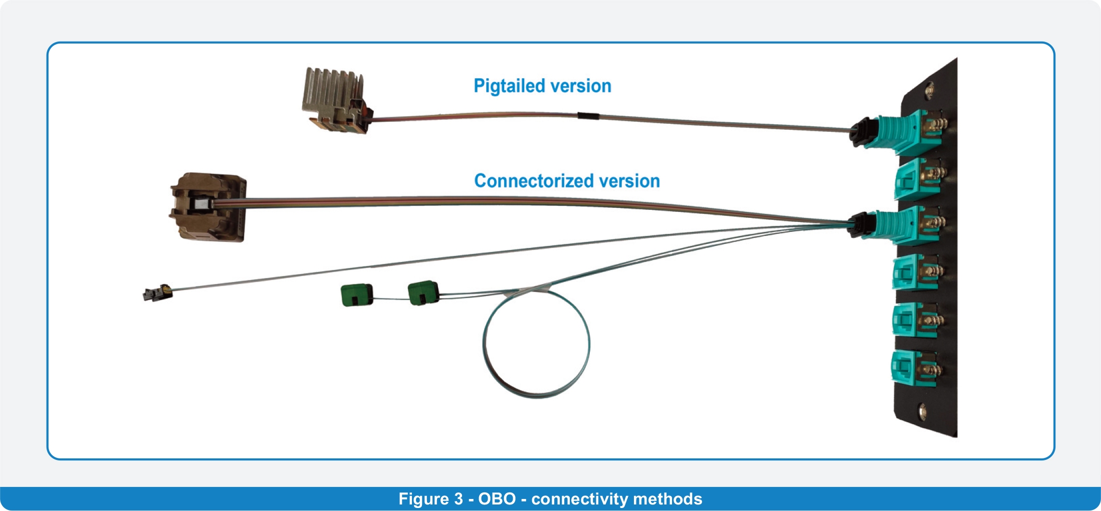
Once the media and the connectors are selected, the harness itself can be manufactured. Two basic types exist: PIGTAILED and CONNECTORIZED (see
figure 3). In the case of the former, the OBO module is directly connected to the optical fibres. The second option utilises the feature of the special ferrule which is attached to the OBO module externally. This approach offers higher flexibility especially during manipulation with the OBO module as there is minimised damage to the media and the module and length of the final product can vary by the length of the connection harness only.
Another important parameter of the media used is its mechanical stability. The cables are sometimes directly terminated into the OBO and represent an essential part of the module. It is crucial to ensure that the module handling/installation does not cause any impact on the fibres which can lead to the malfunctioning of the module itself. If a NON-PEELABLE ribbon is used, the problem is negligible as the ribbon construction provides the necessary protection. Termination of the PEELABLE version must be set such that the ribbon keeps its integrity and will not separate once the module is installed. Ribbon separation results in scrapping of the whole module, which is much more expensive than the raw cable itself. To prevent such a situation on the customer side, it is imperative to evaluate the module + cable combination according the Telcordia GR468 standard, which defines the Generic Reliability Assurance Requirements for Optoelectronic Devices. In terms of the optical harness, one of the most important aspects is defining the mechanical integrity of the media used– cable. It is worth mentioning that the Telcordia GR20 raw cable reliability standard has different levels of acceptance criteria than Telcordia GR468 and therefore it is not sufficient to rely only on the information from the cable manufacturer. This point as well should be on the checklist once the design of the system is under development.
Parameter concerns
As already mentioned, the optical interface on the OBO side and on the face plate side can be based on different materials/solutions. In principle, there are three basic types:
1. Ceramic ferrule – used in single-fibre optical connectors. This design guarantees real physical contact between two mated fibres.
2. Rectangular thermo-plastic ferrule – used in multifibre connectors (MPO, MTP®), which is also designed to ensure physical contact.
3. Special thermo-plastic ferrule which contains an array of lenses. In this case, there is no real physical contact between the fibres and the emitted light must pass two environment changes (ferrule-air and air-ferrule).
The selection of the interface/ferrule has a direct impact on the most important parameter of the optical path – insertion loss.
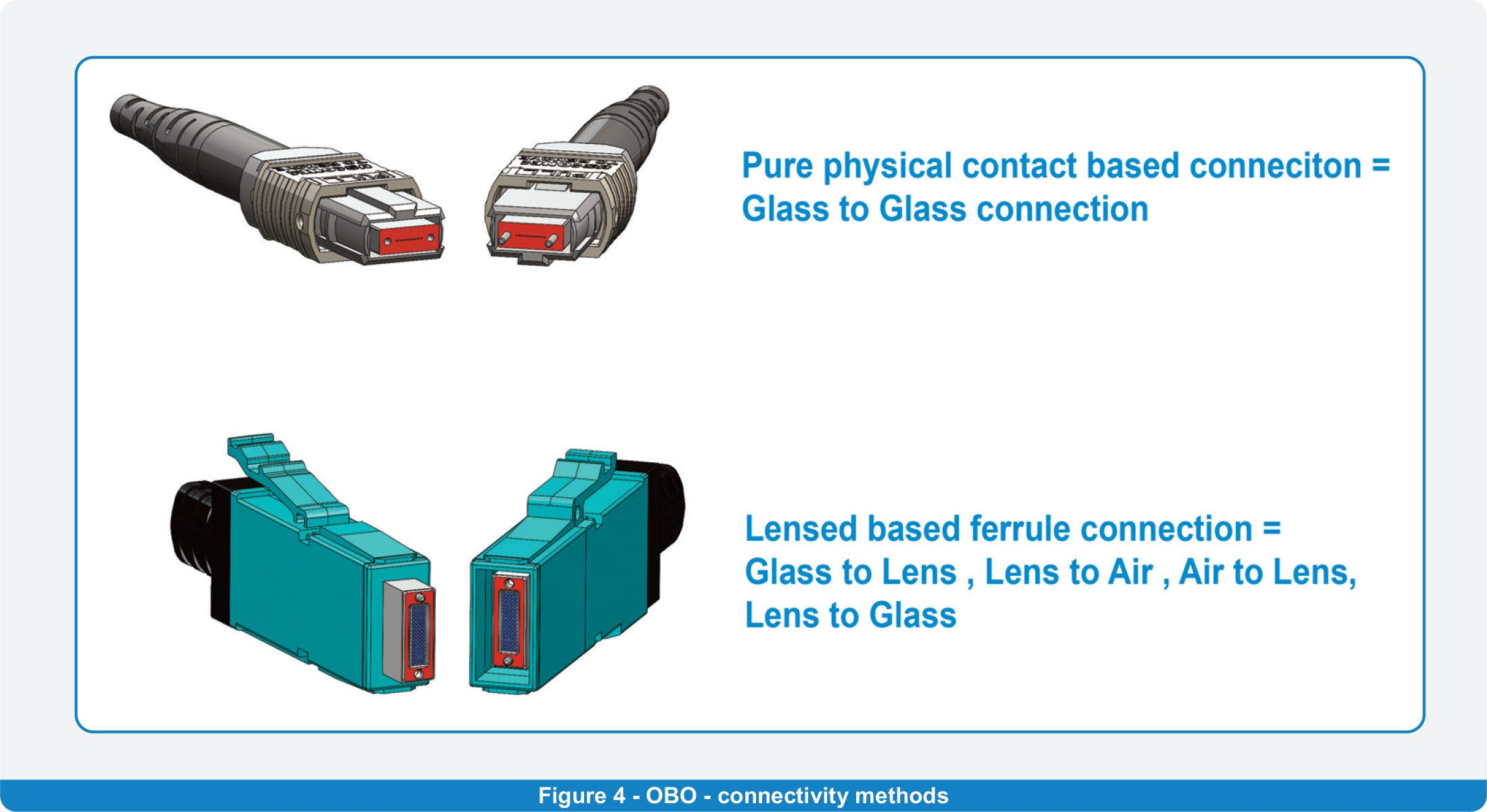
Using the first two of the above-mentioned ferrules, with real physical contact between fibres, the insertion loss values are on the level of 0.3dB. Such values are the typical ones, industry accepted and sufficient for a majority of applications. A different situation arises in the case of lens-based mated interfaces. Insertion loss values vary between 1.2 and 2.2 dB (depending on the design). For projects which are more sensitive to the overall power budget, an enhanced type of lensed ferrules can be used. Enhancing of geometry accuracy and the application of an anti-reflective layer on the end face of the ferrule improves the insertion loss, reaching a level of 0.6 – 1.0 dB. This way the customer can choose the most suit able version for the particular application. Figure No. 4 shows the difference in the area which is in physical contact during the mating of the two connectors and has a direct impact on the optical parameters.
During the procurement process of the harness suppliers – especially the ones offering lens-based ferrule products – is essential to ask for confirmation of the optical parameters measuring procedure used. As lens-based solutions are not traditional, it is important to consider not only the declared maximum values of insertion loss (given by the ferrule manufacturer) but also the complete method of measurement. In general, this method includes four points:
1. Setup of measured path – defining the type of measurement (attenuation related to the individual mated interfaces/ferrules or to complete optical channel).
2. Setting the zero level before the real measurement.
3. Real measurement and value adjustment caused by Fresnel reflections.
4. Comparison of the measured/adjusted values to the pass/fail limit ones given either by the customer or the ferrule manufacturer.
In a nutshell
Harnesses dedicated to connect the OBO module with the outside environment may seem to be technically simple at first glance. Despite this assumption, it is important during the definition part of the project to pay sufficient attention to the:
• Type of connector/interface used on the OBO side and on the outside environment border.
• Construction of the interconnection cable used, with an empasis on the quality criteria defined by international standards.
• Expected levels of optical parameters with regard to the measuring setup/procedure used.
Complying with these basic points put you in a good position to ensure the future functionality of even the most sophisticated products, such as shuffles, and prevent any potential quality issues which could appear once the system is in service – when it can be too late. With Sylex you can count on a simple fact – that we will do everything to identify all the necessary inputs to give you a perfect output.
Sylex is a company which has been active in the fibre optic industry since 1995, offering its experience and professional approach to be the right partner for cases where on-board optic interconnection solutions are required.
Eduard Koza, R&D Manager, Contact
Eduard Koza is R&D manager at Sylex. He started as a project engineer for high-performance copper harnesses. In 2000, he widened his activities to passive fiber optic interconnection products and fiber optic sensing systems. At the beginning of this period, he mainly led multiple technology transfers and covered the implementation of new products into the company portfolio.
Later, he held the role of Engineering manager in the company and headed the technology and engineering activities responsible for transferring customer ideas to the final products. His current position covers the management of newly introduced technical solutions, utilizing his consultancy skills related to customized fiber optic interconnection products.