An ideal multifibre optical harness is expected to have perfect visual aspect of polished fibres, excellent end face geometry and exceptional optical parameters. The fourth essential criterion is the correct connection of the individual fibres within the terminated connectors. By reading this article, you will gain a simple and concise overview of facts related to this topic.
The proper connectivity/polarity of optical harnesses is often considered to be a clear topic with no further question marks. As a consequence, it can happen that insufficient attention is paid to this point, which can lead to serious issues once the complete optical path is perfectly built but not functional. The purpose of this document is not to explain the different polarity types and their functionality, but draw attention to the practical part of their usage depending on the type of transceiver used and its media dependent interface (MDI).
Basic terms:
• Transceiver – active part of the optical channel which contains the receiver (RX) and the transmitter (TX) unit. These days, the most-known types are:
o SFP
o QSFP
o QSFP DD
o CXP/CFP (2, 4)
o CPAK
• Media dependent interface (MDI) – an interface (connector/adapter) of the transceiver through which the optical channel is connected. There are two traditional types (LC, MTP/MPO) and three new evolving types (MDC, SN, CS).
• Polarity – defines the way the particular fibre positions of the two fibre optic connectors are connected within the same fibre optic harness.
• Point-to-Point – direct fibre optic connection of two transceivers without any other fibre optic modules/units.
Single fibre – duplex configurations
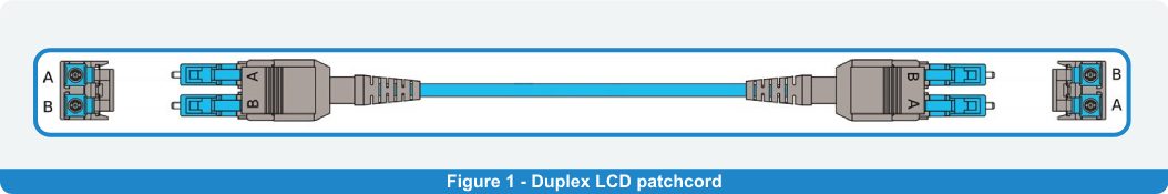
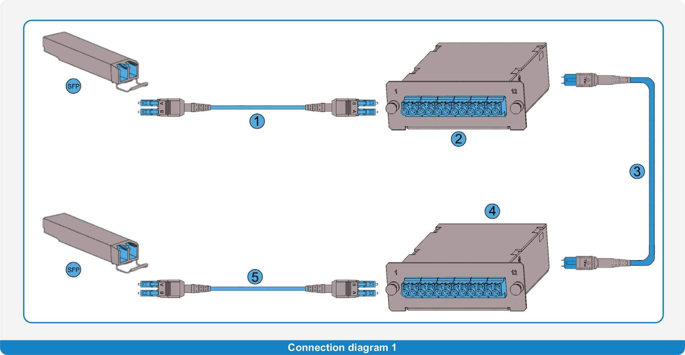
In the case of fibre optic networks based on the transceivers with duplex connectors (mostly LCD), their cross connection is realised by a duplex patch cord/jumper. The LCD connector used has clear markings “A” and “B” on the individual positions of the LC heads. To establish the point-to-point connection, a so-called “A-B” polarity duplex harness is used, which ensures the proper connection of the receiver and transmitter unit on both sides of the optical path. This type of polarity is also referred to as “CROSS”, because the optical signal is led from position A on one side to position B on of the harness (Fig.1). Typical usage is to connect two SFP modules (Fig. 2).
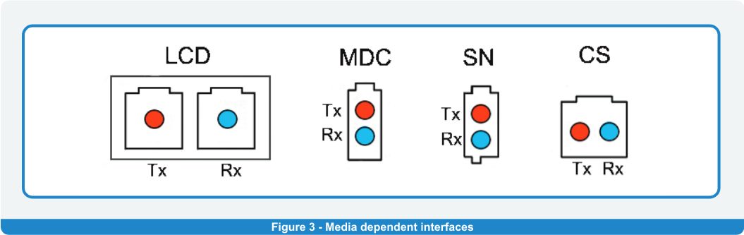
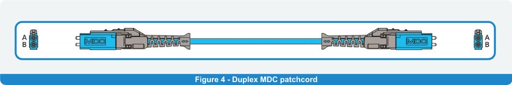
New types of transceivers designed for 200/400G application have their interfaces based on other types of duplex connectors such as MDC, SN or CS. (Fig. 3). All three types create the well-known TX to RX connection using only two fibres, which are cross-connected within the harness, so the polarity is named CROSS (example of MDC version in Fig.4)
Multi fibre configuration
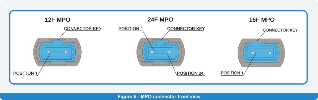
The most-used multifibre connector is the MPO type. There are multiple versions of this connector depending on the fibre count within the ferrule. For transceiver interconnection, the 12, 24 or 16 fibre options are used, where the 24 fibre one has the fibres in two parallel rows. The fibre positions within the connector relative to the connector key are shown in Fig. 5.
12 and 16 fiber option
Using the 12 fibre version of multifibre connector, three different polarity methods are recognised which are described in detail in the TIA 568.3 standard as Type-A:1-1, Type-B:1-1 and Type-C:1-1. The specific wiring of the MPO/MTP harnesses used differs depending on the combination of duplex patch cord and Plug and Play (PnP) cassette used. Those three building blocks are the essential parts of most of the architectures used for the 10G applications in which the multifibre harnesses are being used for the first time. Due to the fact that the 10G solutions are based on the SFP transceivers (with LCD interface), the MPO/MTP harnesses are used as trunk cables for the connection of the PnP cassettes and therefore they do not directly connect the active parts. The polarity selection of the MPO/MTP trunk plays an important role, especially from the future use point of view. In case there is an intention to migrate the existing 10G architecture to the one with higher bandwidth/speed, such as 40/100/400G, the already deployed MPO/MTP trunks can be used for direct connection to QSFP/QSFP DD.
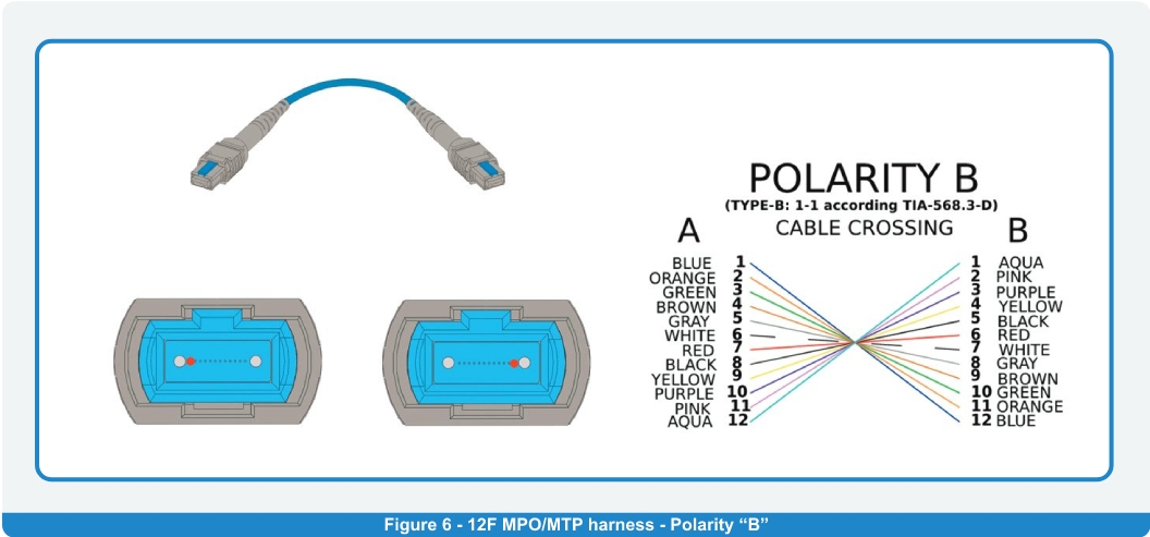
From the migration perspective, the only suitable version is Polarity B (TYPE B: 1-1). The cross-style wiring of lateral positions (marked by the RED dots in Fig.6) of the multifibre connectors used ensures the proper connection of the corresponding TX and RX channels (4+4) of the QSFP/QSFP DD types of transceivers. The MDI of such active parts is showed in Fig. 7.
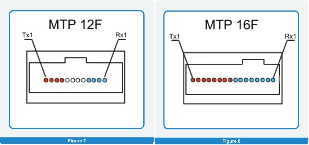
In regard to the MPO/MTP connector of the harness, its position 1 is located in the top-left corner of the ferrule (see Fig. 5). Once this connector is plugged into the MDI of the QSFP active part (Fig. 7), fibres 1 and 12 of the connector will mate with the RX1 and TX1 positions of the MDI, respectively. As the harness used is a Polarity B, it cross-connects position 1 on one side of the harness with position 12 on the other side. As a consequence, the signal from TX1 on one side will enter RX1 on the other side. Similarly, the other TX-RX pairs will be connected. The same principle of TX and RX cross-connection using the Polarity B harnesses is used when the 16 fibre MPO/MTP interface is used – see MDI in Fig. 8, which is specific for QSFP DD transceivers.
24 fiber option
A higher fibre count interface is the 24 fibre one with two rows of fibres. TIA 568.3 recognises three different polarities: TYPE-A:2-2, TYPE-B:2-2, TYPE-C:2-2 (complete overview available here). From the perspective of TX and RX positions within the MDI of a specific transceiver, there are three basic types: CXP/CFP, QSFP DD, OSFP – see Fig. 9.
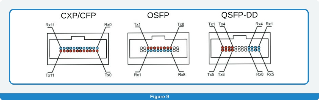
Knowing this, it is important to understand the required connection between them and to choose the MPO/MTP harness with the proper polarity. Based on Fig. 9, for the CXP/CFP and OSFP style of transceivers where the RX channels are in one row and the TX in another, the same type of polarity can be used – the well-known polarity TYPE-A:2-2( SYLEX’s designation Polarity “X”) – see Fig. 10. Corresponding TX-RX pairs are located one above the other, so when using the TYPE-A:2-2 polarity, the two of them will be connected. The situation is different in the case of a QSFP DD transceiver where the TX and RX positions are split a different way. To connect them properly, a harness with different polarity has to be used. Unfortunately, TIA 568.3 does not recognise a polarity which ensures their proper connection. The required harness polarity must set the wiring of the 24 fibre MPO/MTP connectors in such a way that a cross-connection within the same row (position 1 to position 12 – row 1 and position 13 to position 24 row No. 2) will be made. – see Fig. 11 – Polarity B.
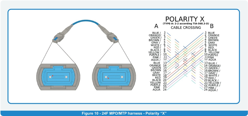
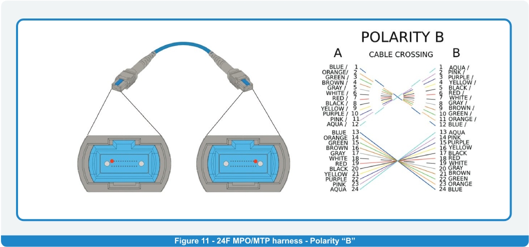
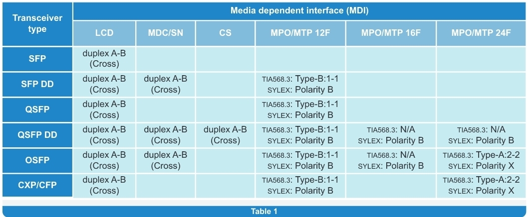
Table 1 shows the complete overview of polarity methods for Point-to-Point connection of typical transceivers depending on the MDI used.
n reality, the Point-to-Point connection is not widely used because of its insufficient flexibility in final applications. Transceivers are mainly used in datacentres where the high modular and complex structured fibre optic cabling infrastructure is required. The optical channel consists of multiple elements such as patch cords, trunk cables, PnP modules, mirroring adapter plates, fanout and migration harnesses. To ensure that the basic principle of each signal path – connect the transmitter and receiver – is fulfilled, each single part of the path should have a proper polarity – not only the main multifibre harness. To do so, a quite complicated definition and checking process should be applied at the design phase, as each element inserted into the optical channel will directly influence the signal routing. At the beginning of this process, it is essential to know the following inputs:
1. Tranceiver
a. Exact types of transceivers used on both sides of the optical channel
b. Media dependent interface (MDI) of all transceivers
2. Optical harnesses
a. Types of connectors used (single/multifibre, fibre count)
b. Quantity
c. Their positoin within the optical channell
3. PnP modules
a. Quantity and position within the optical channel
b. Optical interfaces (adapters used) on the input and output side
c. Inner connection of the PnP module.
d. Keying of adapters (“key-UP/keyDOWN or key-UP/key-UP”) – in the case of multifibre interfaces
4. Adapter plates
a. Quantity and position within the optical channel
b. Types and keying of adapters used
5. Fanout and migration harnesses
a. Quantity and position within the optical channel
b. Wiring/polarity – if any preference exists
c. Types of connectors used
Based on the above-mentioned details, there is the possibility to simulate the complete optical channel, track the optical signal routing and choose the best combination of polarities of all components considering the industry standards.
As a guideline, please see the appendix of this blog where are listed all the standard types of basic configurations which are used in the most of the real cases of multifiber infrastructure.
In case the optical channel or its part is already in place, it is still possible to design and choose the suitable missing or supplementary components in a way which sets up the correct routing between the RX and TX on both sides. As a company with 25 years’ experience in the design and manufacture of passive optical systems, SYLEX is always ready to resolve customers’ specific requirements and issues. This certainly includes the proper polarity definition and monitoring of complex projects during the manufacturing process. For more information, contact us at sales@sylex.sk
Useful links:
[1] Polarities for 12-fibre MTP assemblies (1-S-2657)
[2] Polarities for 16-fibre MTP assemblies (1-W-8063)
[3] Polarities for 24-fibre MTP assemblies (1-S-2663)
APPENDIX
Sylex recommended polarity connections
10G applications (SFP transceivers)
12 FIBER VERSION
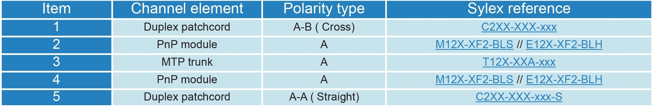
Based on 12 fiber MTP trunk cable polarity A ( TIA568.3: Type-A:1-1)
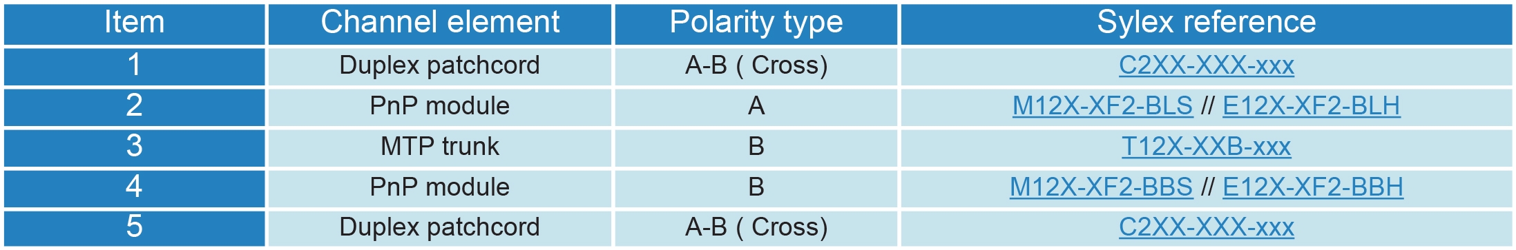
Based on 12 fiber MTP trunk cable polarity B (TIA568.3: Type-B:1-1)
Based on 12 fiber MTP trunk cable polarity C ( TIA568.3: Type-C:1-1)

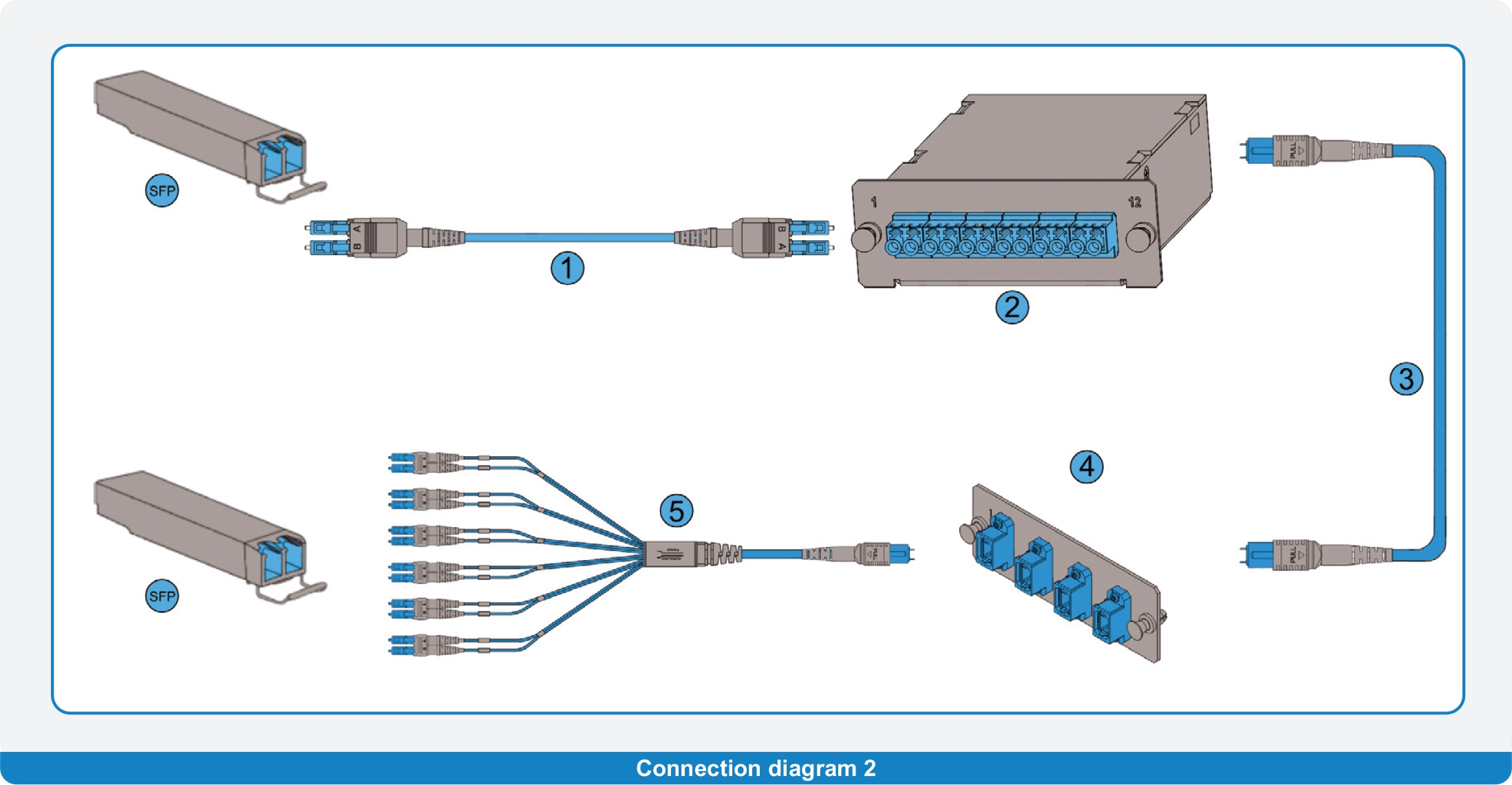
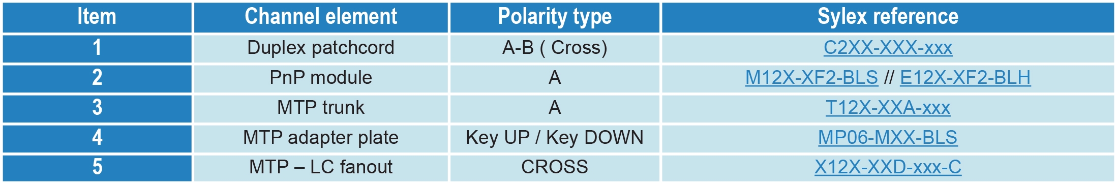
Based on 12 fiber MTP trunk cable polarity A ( TIA568.3: Type-A:1-1) + MTP-LC fanout
Lorem ipsum dolor sit amet, consectetur adipiscing elit. Ut elit tellus, luctus nec ullamcorper mattis, pulvinar dapibus leo.
24 FIBER VERSION
Based on 24 fiber MTP trunk cable polarity X ( TIA568.3: Type-A:2-2)
Notes:
• All MPO/MTP adapters in PnP boxes are KEY/UP – KEY/DOWN type
• All versions are available in single-mode and multimode version
• Under a condition of using KEY/UP – KEY/DOWN MTP adapters any additional count of Polarity “A” MTP trunks (as an extender)
can be used utilizing the same functionality of the complete channel.
40G and 100G applications (QSFP transceivers)
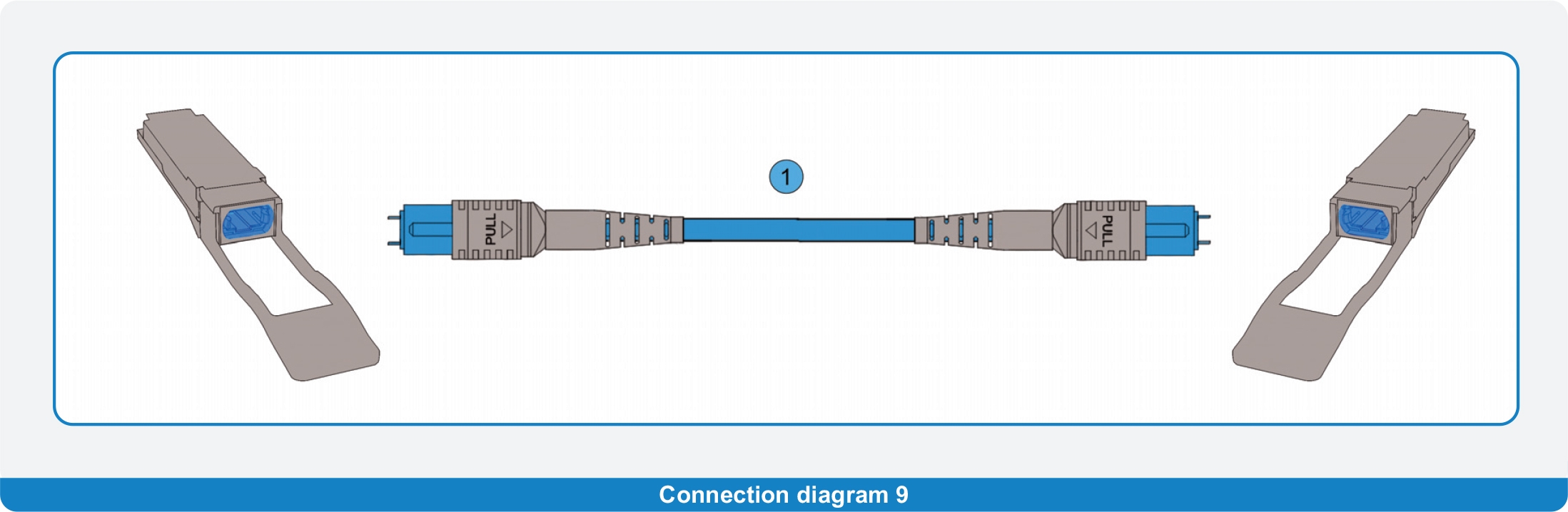
Direct connection of QSFP transceivers
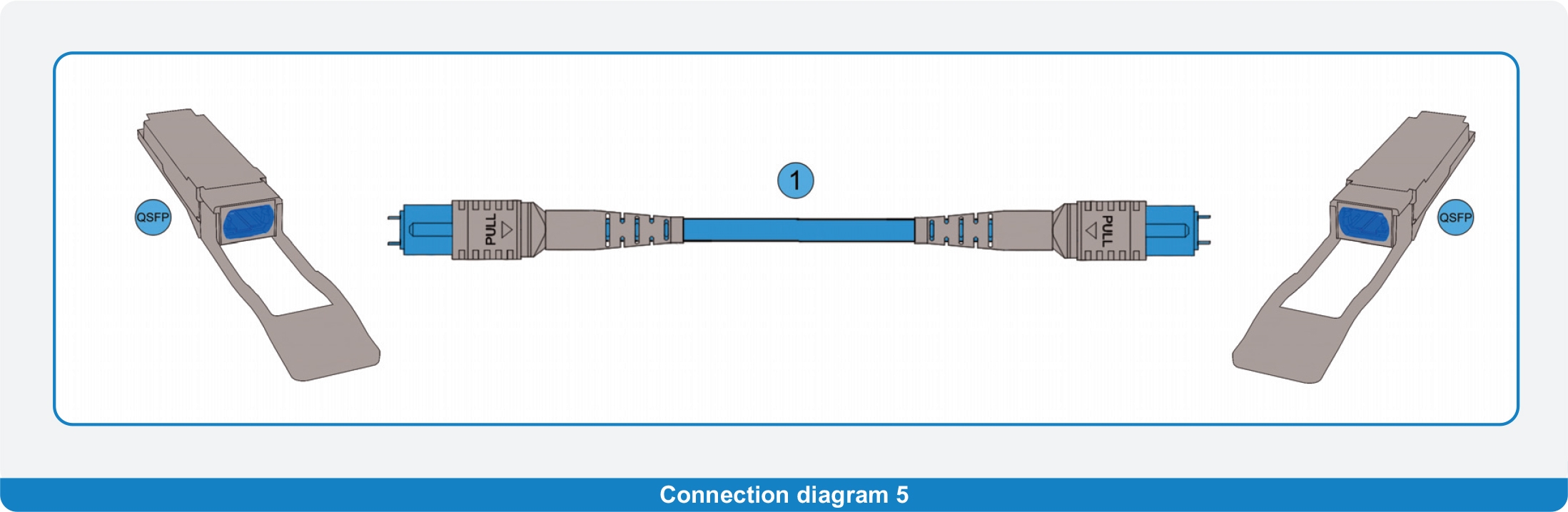

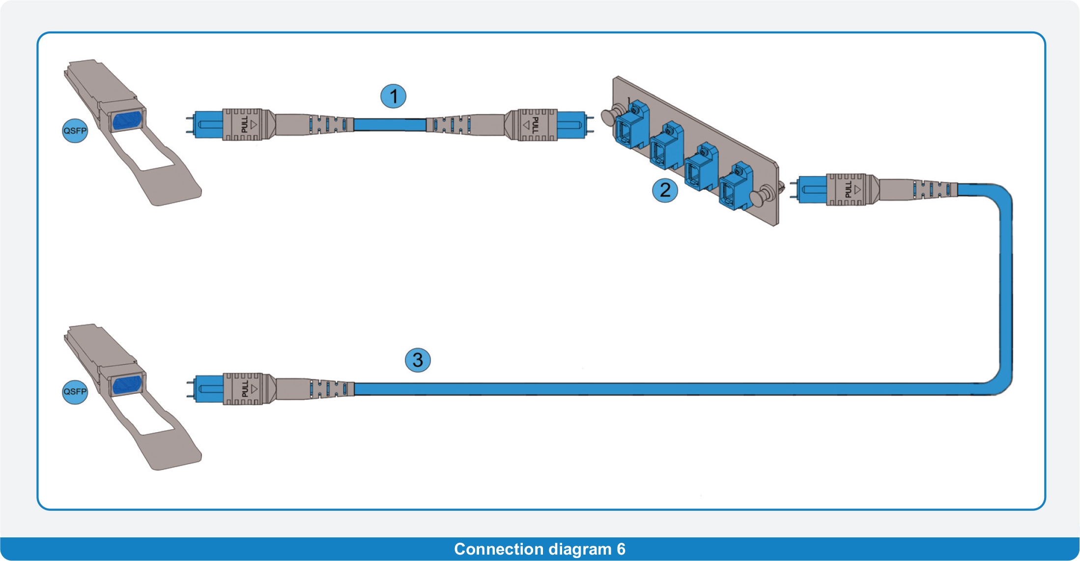
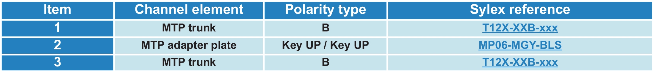
Direct connection of QSFP transceivers + extender trunk
Notes:
• Under a condition of using KEY/UP – KEY/UP MTP adapters any additional count of Polarity “B” MTP trunks (as an extender)
can be used utilizing the same functionality of the complete channel
QSFP to SFP transition harness
Direct connection of QSFP and SFP transceivers
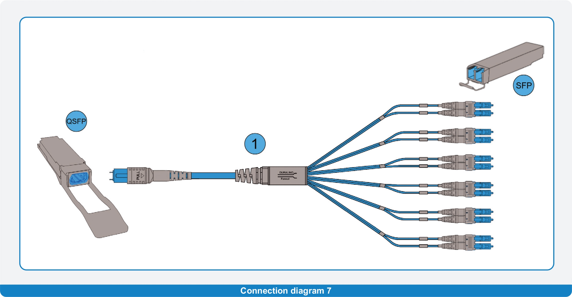

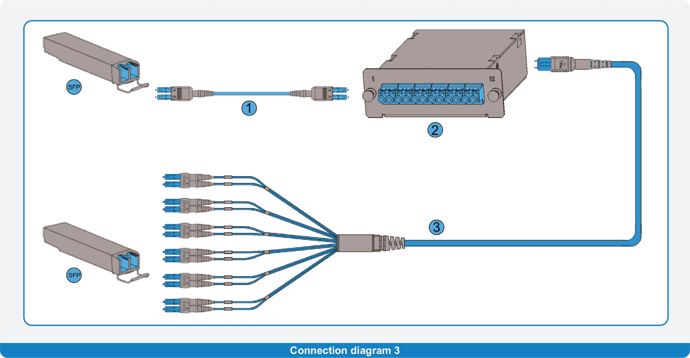
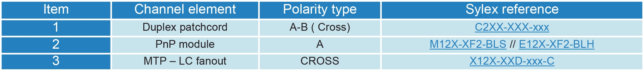
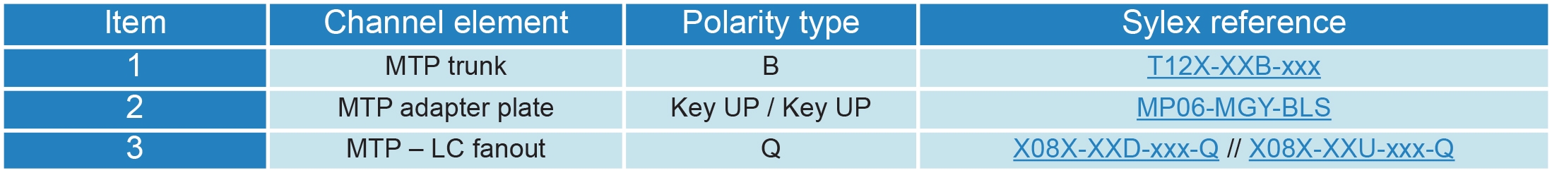
MTP trunk + LC fanout
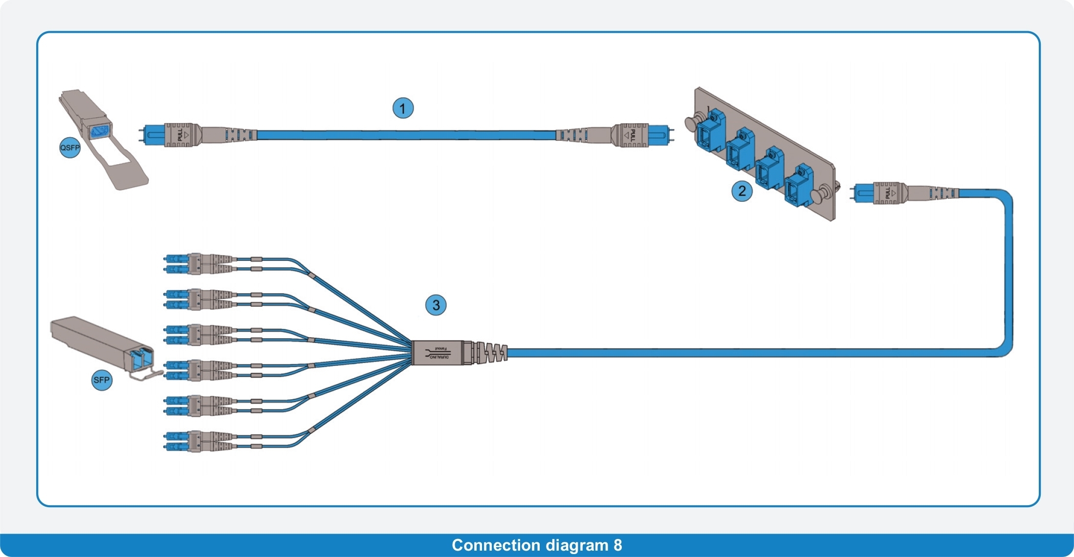
Based on 24 fiber MTP trunk cable polarity B ( TIA568.3: Type-B:1-1) and MTP-LC fanout for direct connection of QSFP and SFP transceivers
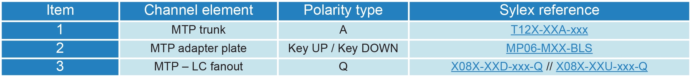
Based on 12 fiber MTP trunk cable polarity A (TIA568.3: Type-A:1-1) and MTP-LC fanout for direct connection of QSFP and SFP transceivers
Notes:
• Under a condition of using KEY/UP – KEY/UP MTP adapters any additional count of Polarity “B” MTP trunks (as an extender)
can be used utilizing the same functionality of the complete channel
• Under a condition of using KEY/UP – KEY/DOWN MTP adapters any additional count of Polarity “A” MTP trunks (as an extender)
can be used utilizing the same functionality of the complete channel
CXP / CFP / OSFP / QSFP DD harnesses – 24 fiber one
Direct connection
Connection of CXP, CFP or OSFP transceivers

Connection of QSFP DD transceivers

Notes:
• Under a condition of using KEY/UP – KEY/UP MTP adapters any additional count of Polarity “B” MTP trunks (as an extender)
can be used utilizing the same functionality of the complete channel
• Under a condition of using KEY/UP – KEY/DOWN MTP adapters any additional count of Polarity “A” MTP trunks (as an extender)
can be used utilizing the same functionality of the complete channel
Eduard Koza, R&D Manager, Contact
Eduard Koza is R&D manager at Sylex. He started as a project engineer for high-performance copper harnesses. In 2000, he widened his activities to passive fiber optic interconnection products and fiber optic sensing systems. At the beginning of this period, he mainly led multiple technology transfers and covered the implementation of new products into the company portfolio.
Later, he held the role of Engineering manager in the company and headed the technology and engineering activities responsible for transferring customer ideas to the final products. His current position covers the management of newly introduced technical solutions, utilizing his consultancy skills related to customized fiber optic interconnection products.