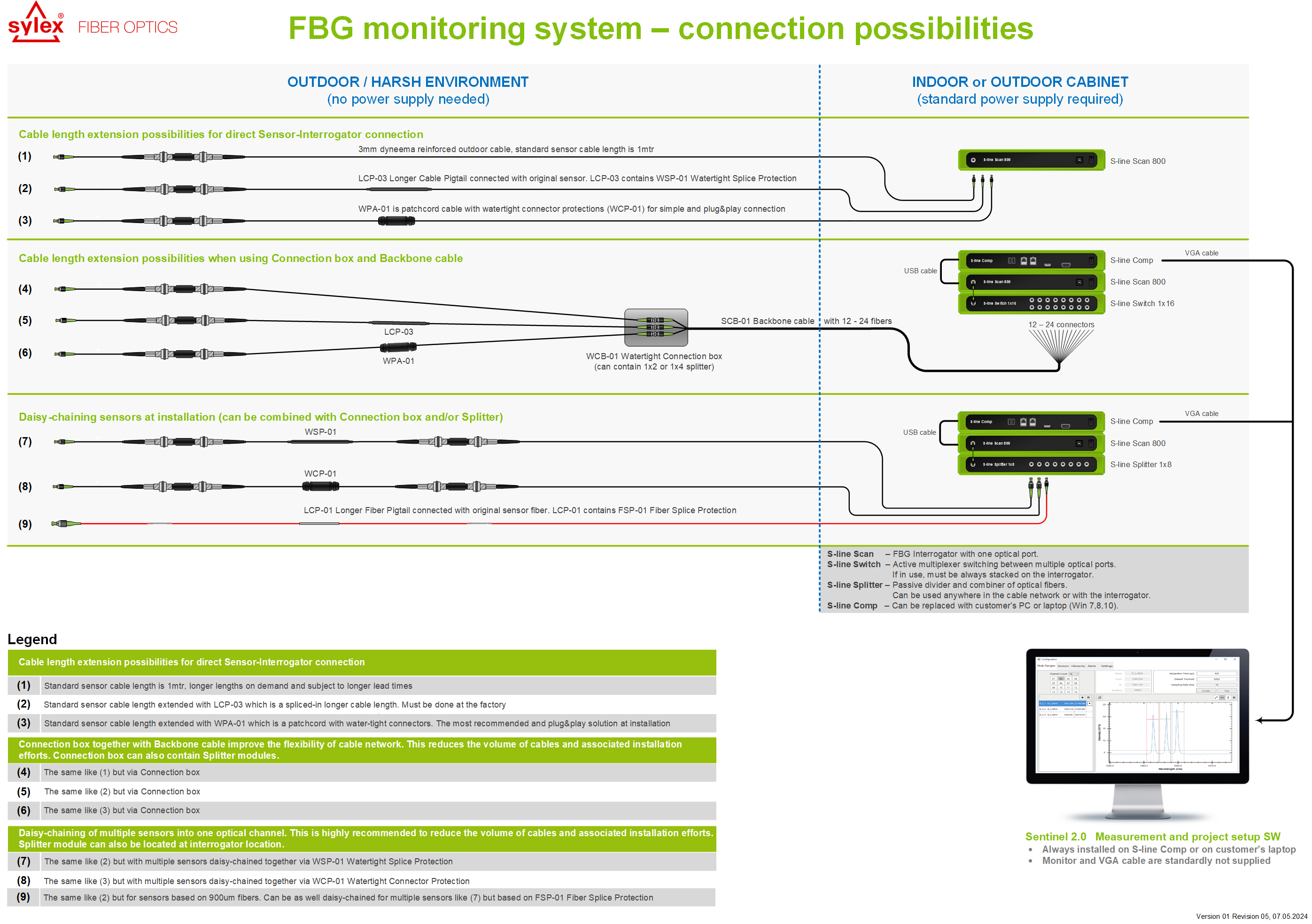
A Connections diagram for fiber optics sensors typically illustrates the various components involved in setting up and utilizing fiber optic sensors. This diagram typically includes:
Fiber Optic Sensor: The central component, which detects changes in light intensity or other parameters along the optical fiber.
Light Source: A source of light, often a laser or LED, which emits light into the optical fiber.
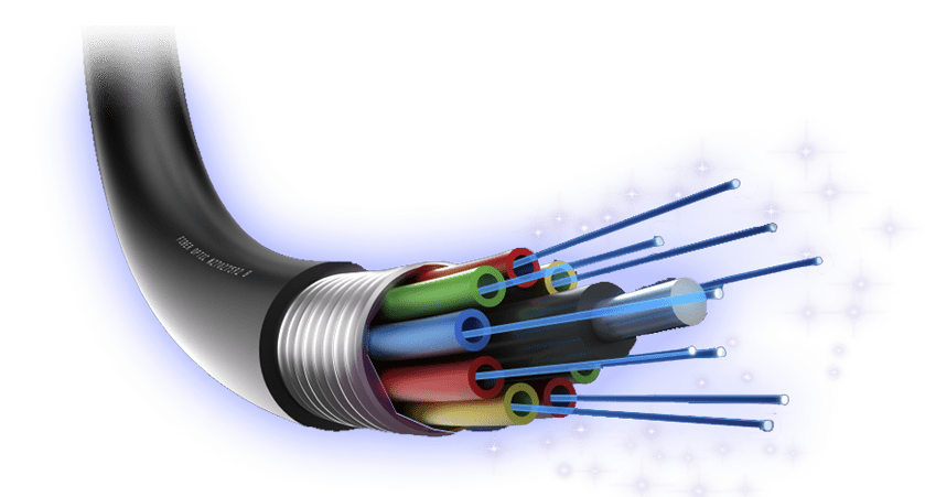
Optical Fiber: The medium through which light travels from the light source to the fiber optic sensor. It’s usually a thin, flexible, transparent fiber made of glass or plastic.
Detector: This component receives light from the fiber optic sensor and measures its intensity or other characteristics. It may be a photodiode or other light-sensitive device.
Signal Processing Unit / Interrogator: The unit that processes the data received from the detector, often converting it into a usable form for display or further analysis.
Control Unit: Sometimes included, this unit regulates the operation of the light source, detector, and signal processing unit.
Power Supply: Provides electrical power to the various components of the system.
The diagram typically shows how these components are interconnected using optical fibers and electrical cables, indicating the flow of light and data within the system. It may also include labels and annotations to clarify the function of each component and the direction of signal flow.