Eduard Koza1 , Jozef Pavlov1 , Ivan Golian2 Department of Engineering1 , Quality department2 Sylex s.r.o., Mlynské luhy 31, 82105 Bratislava
Abstract
The increased demand for datacenters rose up the question about the connections performances necessary for two network point’s interconnection. This white paper deals with the present and future possibilities of managing a datacenter by using the available technology for interconnections based on multifiber connectors such as MTP®.

1. Introduction
During the present increased demand on datacenter applications a question about length and number of connectors that may be between two network points appears more frequently. There are also a couple of reasons which are driving the need for higher networking data rates like FCoE, virtualization, Quad (Eight) Core processors, network convergence. This data rate increase is challenging and influencing the quality/performance of the physical layers. On top of that this issue has a big justification as TIA-568-C.0 standard declares that any 10 Gb line built on OM3 cables may have the maximum insertion loss of 2,6dB. System and subsystem manufacturers face the request of two basic but very difficult requirements. First is a clear declaration of total line loss (2,6dB). Second is a continued growth and churn in the data centers which causes challenges in physical network implementation.
2. Changes in datacenter
Datacenter managers are moving away from ridged point to point type architectures to more manageable/scalable structured cabling architectures with high density multifiber connector’s. This means there is very difficult to predict a final amount of connector mating’s points. Under these uncertain conditions, the only possibility to meet the power budget is to offer the products, which parameters will convince the customers of their suitability for the whole application being prepared. Furthermore, they should be pre-prepared for other applications such as 40 or 100GB which limit values of IL budget per route are even stricter. (See table 1).
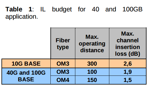
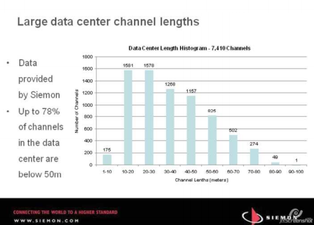
These high performance networking systems are based on OM3 or OM4 multimode fiber types which typical loss value cannot exceed 3.5dB/km at 850nm, according to IEC 60793. From general industry experience (Siemon’s findings), a proven evidence is that in average the individual connection cables used in datacenter applications are in short length (Fig. 1).
Nevertheless, a situation in which the whole line or even only one connection cable will be on the limit of maximum length of 300m may occur. Real installation practices (tie wraps, excessive cable bends, etc…) cause increase of the link insertion loss (IL). Also cable assemblies are patched together or concatenated in a structured wired architecture adding additional (perhaps unplanned) physical link lengths and additional insertion loss with transition from MTP® to LC for 10GbE. These new structured cabling provide increased physical layer flexibility and manageability but also may add cable length and connector mated pairs in the link. Datacenter managers are requiring the flexible manageable cabling network with the guarantee of meeting future link performance requirements. Structured cabling solutions implemented with high density MPO / MTP® connectors provide the datacenter manager with a high level of manageability and flexibility, however low performance optical assemblies may cause networking performance issues when scaling data rates, reconfiguring the network, or with poor installation practices thus mitigating the effort of installing a high density structured wired cabling network.
Another determining element besides the cable is the two connector types configuration, mainly in LC duplex and MPO / MTP® version. LC connectors are currently the standard for any optical application and optical community has no doubts about their parameters (with respect to reputable manufacturers). MPO/MTP® type connectors could be in configuration of 8F to 72F. Slowly but surely, they get outstanding eminence in specific applications like a broadly accepted high performance optical connector solution with a highly growing scale of installation.
Sylex, s.r.o., as one of the MT connectivity leader in European market, took a request of max IL budget as a challenge. The company’s program covers a complex range of products intended for datacenter applications. As stated before, most of the products are mainly based on MTP® / MPO and LC connectors where the MT side can alternatively be realized from two “mutations” of MT connectors, i.e. MPO or MTP®. Both connectors are fully compatible with each other, but MTP® type connectors from USConec have several slight but very important improvements:
- Removable housing for gender change and rework
- Metal pin-clamp (Eliminates lost pins, Centers spring force and Eliminates fiber damage from spring)
- Recessed pin clamp to prevent springribbon contact Oval spring for more ribbon clearance
- Increased ferrule float for improved mechanical performance (US patent 6,085,003)
- Elliptical guide pin tip for improved durability via less guide-hole wear (US patent 6,886,988)
These improvements contributed to the decision that the whole Sylex’s MT program is based on the connectors which characteristics can be summarized in “The MTP® connector is a high performance MPO!”
3. Test requirements
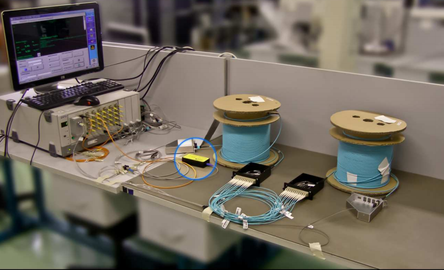
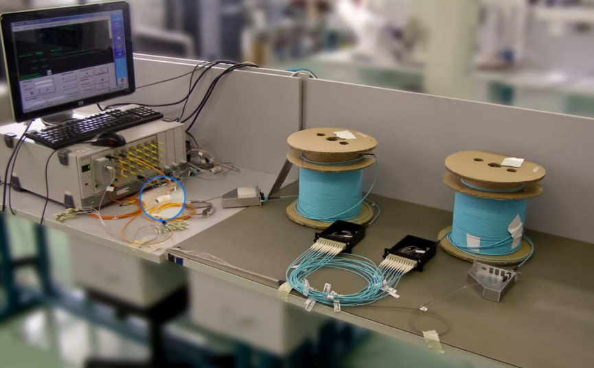
Because a declaration of product parameters in datacenter applications is clearly defined, a test of real configuration, represented by a typical connection of 10 Gb line in datacenter from the connection point of view, has been performed within Sylex, s.r.o. It considers the maximum possible length of 300m though. Another important factor is that all MTP® connections were of random type. This means that also connectors used in measuring and auxiliary cables (from and to the measuring equipment) were of the same quality like measured connectors.

In general, requested definitions (based on the normative) can be summarized as:
- length of max. 300 m
- number of connectors – theoretically unlimited
- max. line loss of 2,6 dB
Test assumptions: LC connectors:
- IL<0,35dB; mean value SYLEX 0,034dB
- MTP® connectors: IL< 0,.5dB; mean value SYLEX 0,035dB
- Cables based on OM3 fiber with declared loss of 2,5dB /km at 850nm commercially available from European manufacturer
Tested product:
10 Gb link with the length 300m and 6 mated pairs composed of following standard products:
- 2 x MTP®(M)-SC 12F OM3 fanout, 2M
- 2 x MTP®(F)-MTP®(M) 12F, OM3, 147M
- 2 x Plug&Play cassette MTP® – 12x LC, OM3, 0,35M
- 12 x LC-LC OM3 SXJP, 1,3M
3.1 Measured results
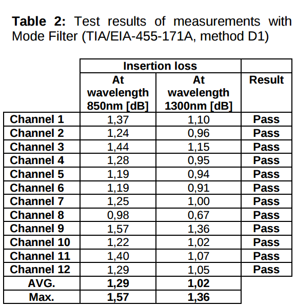
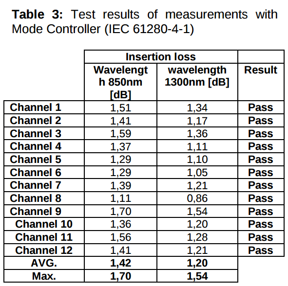
Important point of the whole measurement is the fact that it was performed at two different conditions. First option is to measure the whole line using TIA/EIA-455- 171A mode filter commonly used under conditions of all manufacturers. Main reason was its simplicity and primarily affordable price. The second option is to use mode controller, which forms conditions of EFLUX (encircled flux launch condition on 50um fiber; 850/1310nm) measurement defined in IEC 61280-4-1. Manufacturers don’t use this method mainly due to its costs as mode controllers are very expensive. Important information is that almost always the values measured by mode controller are less favorable than values measured by mode filter.
Measurements done within Sylex, s.r.o. were performed by using both methods to confirm that results in compliance with TIA-568- C.0 standard for 10GbE OM3 lines can be achieved even under the hardest test conditions.
To offer the total overview, all measured values (Table 1 and Table 2) are listed, not only the average values. Single fiber connectors are virtually connectors of grades declared in IEC 61753. Commonly, customers choose required quality class of connectors for IL budget calculation based upon a “mean” value while also max value for more than 97% of tested samples is known. In evaluation of our measurement we emerge from the worst values to simulate the most unfavorable situation in a specific prospective application.
3.2 Evaluation
Max. reached loss value of the whole tested line:
- with mode filter (MF) it is 1,57dB (at 850nm), and
- with mode controller (MC) it is 1,7dB (at 850nm). (assumption of worse value was confirmed with this measurement type)
Based on simple calculation it is visible that to the standard requirements the whole line has still an IL headroom of 1,03dB (MF), or 0,9dB (MC) compared with max value of 2,6dB. There are 6 optical mated pairs in the whole line while 4 of them are based on MTP® connectors. According to the fiber manufacturer, the fiber loss itself is 0,75 dB for 300 m. Joints themselves have 0,82 dB (MF) or 0,95 dB (MC). If we would do a very rough extrapolation, one optical joint on the whole line will represent a loss of 0,137dB (MF) or 0,159dB (MC). To achieve limits defined by the standard this line could include additional 7 (MF) or 5 (MC) optical mated pairs (under a condition that the link length is the maximum one and the whole IL headroom should be used for connections only). Despite the fact that the extrapolation is not fully accurate we get a total overview about IL headroom for additional optical joints that is available in the whole testing chain. This link loss budget headroom or margin may be used also to absorb poor installation practices such as tight cable bends, tie wraps and new future applications, such as structured cabling.
Important conclusion of the whole measurement is also a finding that this kind of line is in means of the loss suitable also for 40Gbps or 100Gbps applications, which have IL limit set to 1.9dB for OM3 while its maximum length is 100m. If we would shorten the whole line to 100m for OM3 and keep the number of optical joints, the spare space of IL budget set for 40 Gbps and 100 Gbps will be:
OM3 cable 0,83 dB (MF) and 0,7 dB (MC); IL limit according to IEEE 802.3ba (max 1,9dB)
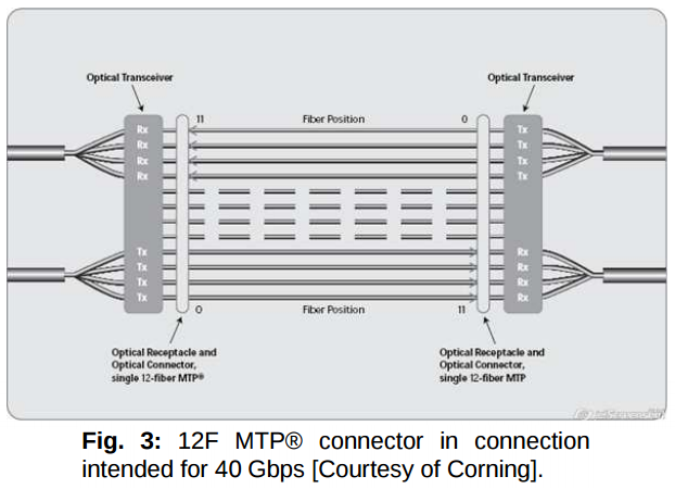
Of course, a claim that 40 and 100 Gbps systems will most likely be built on parallel transfer might rise. Especially in case of 100 Gbps it would concern 24F MTP® joints which might have worse IL values than the tested 12F ones. It is necessary to mention that there is already a technology published for example by Altera which demonstrates transfer rate of 25 Gbps. Thus, in theory, also 12F MTP® connector in connection intended for 40 Gbps is able to transfer 100 Gbps. (Fig. 3)
4. Conclusion
Test of 300m long OM3 line built on combination of LC and MTP® connectors has shown that it is possible to build a configuration compliant with the standard for 10 Gbps transfers without any problems and that it still has a link loss headroom of almost 40% of IL budget. It is more than optimistic to state that the very same line is suitable also for transfers requiring rates of 40 to 100 Gbps. Here we have to note that the 40/100 Gbps systems will run on the parallel solutions therefore the whole link loss headroom from the singlefiber LC connectors is available as well. However, a necessary assumption is to have materials of outstanding quality which in our case are represented by products from USConec. Know how of manufacturing and polishing processes of company Sylex is of the same importance that can ensure optical and geometrical parameters on the level needed to comply with IL limits of 2,6 dB for 10Gbps and 1,9 dB for 40&100 Gbps.
7. Appendix